Macaos Integrated Test Jig
 The Macaos Integrated Test Jig is a new design which integrates test circuitry into a modular test jig. It is developed for increased reliability and ease of design, compared to the Box Jig or the Legacy Jigs.
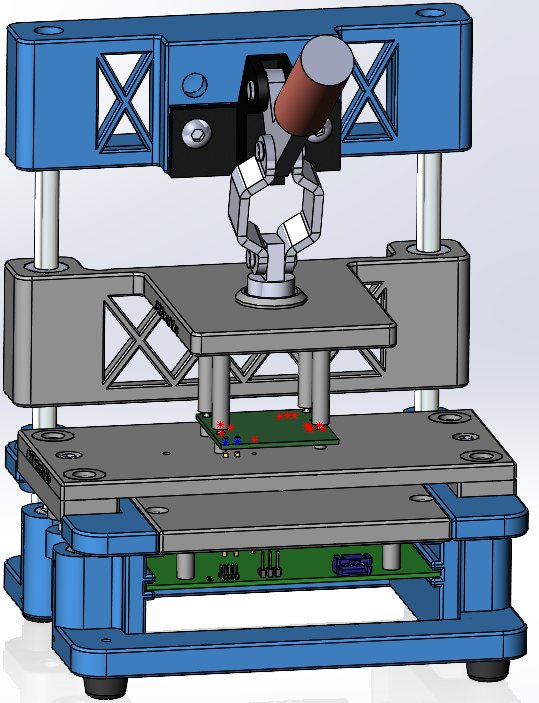
A PCB with test circuitry is located in the base of the jig, and the test pins are soldered into this PCB.
The user selects an active area size, and then specifies the locations and types of Guide Pins and Test Pins. From this information, the Upper Fixture, Protective Cover and Receptacle Plate (the three gray modules shown at the right) are generated and added to the jig. In addition, a Gerber file with the pin locations and profile of the Test Circuitry PCB is automatically generated.
The fixture specifications (in mm) are:
| Active test area width (X-dimension) | 80/100/120/140/160/180 |
|---|---|
| Active test area depth (Y-dimension) | 60/70/80/90/100/110/120/130/140/150 |
| Test electronics PCB width (X-dimension) | Active test area width + 20 |
| Test electronics PCB depth (Y-dimension) | Active test area depth + 40 |
| Clearance above/below PCBA under test | 34/4.5 |
| Clearance above/below test circuitry PCB | 12/33 |
| Test circuitry PCB thickness | 1.6 |
Macaos Box Jig
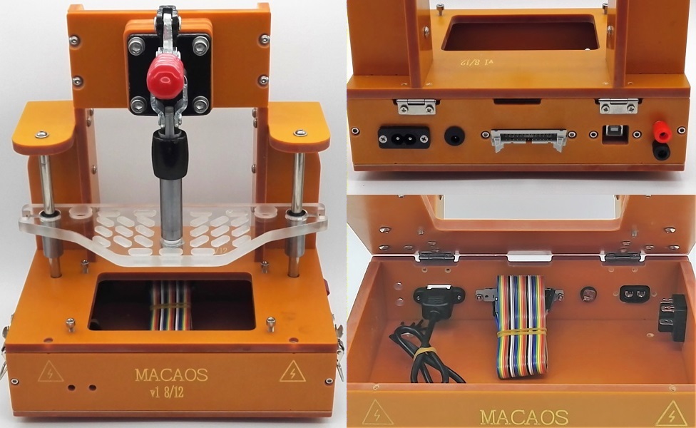
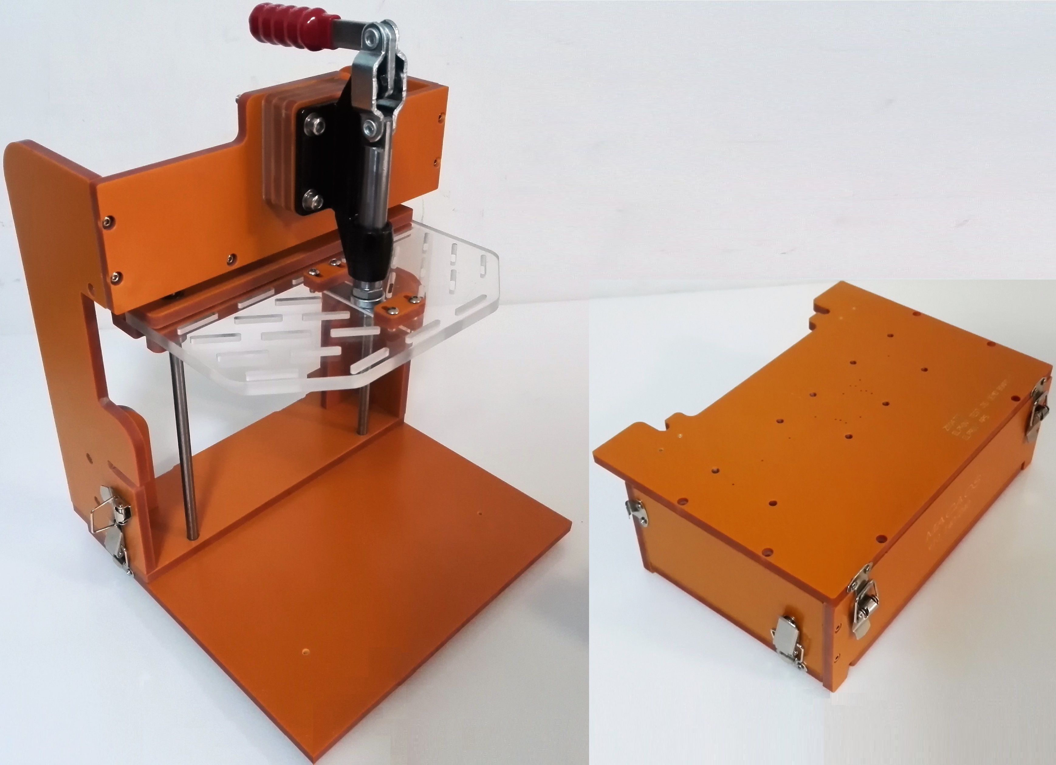 The Macaos Box Jig is a test jig where the lower fixture is a box deep enough to contain test electronics, as well as connectors mounted in the side walls. Both the top and bottom of the lower fixture box are hinged, in order to give easy and flexible access.
The standard lower fixture has holes drilled for the test pin receptacles.
An alternative is to have a large opening in the lower fixture, over which a PCB is placed. In this case, a Gerber file specifying the board outline, mounting holes and test pin locations is generated. This Gerber file may be imported to a CAD system for designing the PCB.
The jig is supplied with an upper fixture. This fixture has slots for placing press pins as needed to insure good contact between the PCBA and the test pins in the lower fixture.
In the Macaos Box jig, both fixtures are easily replaced. The lower fixture is held in place with two latches. The upper fixture is held in place with two thumbscrews and a magnet.
The fixture specifications (in mm) are:
| Fixture type | Lower | Lower w/PCB | Upper |
|---|---|---|---|
| Active area width (X-dimension) | 240 | 70–240 | 240 |
| Active area depth (Y-dimension) | 140 | 70–140 | 140 |
| Fixture width (X-dimension) | 260–500 | 300–500 | 240 |
| Fixture depth (Y-dimension) | 160–500 | 160–500 | 60–500 |
| Fixture height/thickness (Z-dimension) | 91 | 91 | 8 |
Legacy Jig
 The Legacy Jig is a simple test jig, where the lower fixture is attached to a deep base. With the legacy fixture, the “box” is part of the jig (rather than part of the fixture, as with the Box Jig). The Legacy Jig is available in three sizes.
The lower fixture may be a single plate or a box which fastens onto the jig base.
The jig is supplied with an upper fixture. This fixture has slots for placing press pins as needed to insure good contact between the PCBA and the test pins in the lower fixture.
The fixture specifications (in mm) are:
| Fixture type | Lower (flat) | Lower (box) | Upper |
|---|---|---|---|
| Active area width (X-dimension) | 120/200/260 | 120/200/260 | 120/200/260 |
| Active area depth (Y-dimension) | 80/120/150 | 80/120/150 | 80/120/150 |
| Fixture width (X-dimension) | 160/240/300 | 170/260/320 | 160/155 or 216/364 |
| Fixture depth (Y-dimension) | 100/140/170 | 108/150/180 | up to 500 |
| Fixture height/thickness (Z-dimension) | 8 (2–20) | 33 (33–100) | 8 (2–20) |
Custom size
A custom size fixture may be designed for use with other test jigs.
The fixture specifications (in mm) are:
| Fixture type | Lower (flat) | Lower (box) | Upper |
|---|---|---|---|
| Active area width (X-dimension) | 0–500 | 0–500 | 0–500 |
| Active area depth (Y-dimension) | 0–500 | 0–500 | 0–500 |
| Fixture width (X-dimension) | 0–500 | 0–500 | 0–500 |
| Fixture depth (Y-dimension) | 0–500 | 0–500 | 0–500 |
| Fixture height/thickness (Z-dimension) | 8 (2–20) | 33 (33–100) | 8 (2–20) |